Your Honeywell humidifier has stopped producing moisture, leaving dry winter air aggravating your sinuses and damaging wood furniture. When the unit remains silent despite low humidity readings, power issues or water supply failures are likely culprits. This guide delivers precise troubleshooting steps for both drum-style and flow-through Honeywell models using only essential diagnostic tools. You’ll systematically isolate failures in power supply, water delivery, and control systems to restore operation without professional help.
Power Supply Verification Procedures
Begin by confirming electrical connectivity since furnace-dependent power systems cause frequent operational failures. Honeywell humidifiers draw power exclusively from the furnace control board—not standard household outlets—making furnace diagnostics critical.
Test Furnace Control Board Output
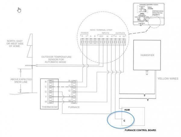
Disconnect power to your furnace before proceeding. Locate the humidifier connection terminals on the furnace control board (typically labeled “HUM” or “HU”). Set your multimeter to AC voltage mode and place probes on these terminals while the furnace runs a heating cycle. A proper 24-volt AC reading confirms the board functions correctly. No voltage indicates control board failure, requiring replacement using your furnace model number—not the humidifier model—for compatibility.
Check Transformer Voltage Supply
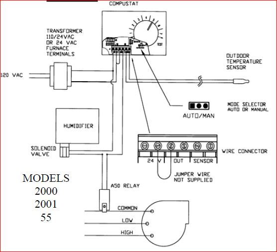
Some systems use a dedicated 24-volt transformer for humidifier circuits. If your humidistat clicks when adjusted but the water inlet valve shows no response, test the transformer output. With power restored, measure voltage across the transformer’s output wires. Absence of 24 volts confirms transformer failure. Replace it with an identical unit matching both voltage (24V) and VA rating (typically 40VA), as undersized transformers cause intermittent operation.
Water Supply System Diagnostics

Water flow interruptions account for the majority of humidifier failures. These components fail predictably due to mineral buildup or mechanical wear, requiring systematic testing.
Saddle Valve Failure Identification
The saddle valve clamped to your copper water pipe frequently clogs with sediment. If household water pressure remains normal but no water enters the humidifier, this valve is suspect. Critical diagnostic step: Verify voltage at the water inlet valve terminals during operation. If 24 volts registers but zero water flows, the saddle valve—not the inlet valve—is faulty. Cleaning rarely resolves this; replacement is necessary. Turn off your main water supply, cut the copper pipe, and install a new saddle valve with compression fittings.
Water Inlet Valve Operation Test
This valve opens electronically to admit water when the system activates. With power applied, use your multimeter to confirm 24 volts at the valve’s electrical terminals. Voltage present without water flow confirms mechanical valve failure due to mineral deposits. Replace the valve immediately, ensuring new compression fittings seal the connections to prevent leaks. Never attempt to disassemble stuck valves, as internal components are non-serviceable.
Drum-Style Component Troubleshooting
Drum humidifiers rely on rotating media and precise water regulation. Failures here manifest as silent operation or inadequate moisture output despite power and water supply.
Drive Motor Continuity Testing
Power off the furnace and disconnect the motor wiring harness. Set your multimeter to continuity mode and touch probes to the motor terminals. No continuity beep (open circuit) confirms motor failure. Before replacing, verify voltage reaches the motor during operation—24 volts present with no rotation definitively indicates motor replacement is needed. Most drum motors install in under 15 minutes using standard screwdrivers, but always match your humidifier model number when ordering.
Float System Obstruction Check
The float regulates water level by rising with the tray’s fill height to shut off the inlet valve. Remove the humidifier cover and manually lift the float. If it sticks or moves unevenly, mineral buildup or cracks are blocking operation. Inspect for physical damage like cracks or warping that prevents proper sealing. A damaged float won’t trigger the inlet valve to close, causing overflows or dry operation. Replace it using your humidifier model number, as universal floats often create sealing issues.
Control System Component Testing
Humidistats and control valves work as an integrated system—failure in either halts operation. Diagnose these components using electrical verification before replacement.
Humidistat Contact Verification
Set your multimeter to continuity mode. Turn the humidistat dial above current room humidity (e.g., to 50% when actual humidity is 30%). No continuity across the humidistat terminals confirms failed internal contacts. This occurs when oxidation or wear prevents electrical closure. Replace the humidistat using wiring diagrams specific to your furnace model, as universal units may not match voltage requirements. Never bypass humidistat wiring, as this risks uncontrolled moisture damage.
Water Panel and Tray Inspection
For drum-style units, inspect the evaporative media (water panel) for mineral crust or disintegration. A clogged panel blocks moisture release even with proper water flow. Remove the panel and hold it against light—if you can’t see through it, mineral deposits have sealed the pores. Replace panels annually, matching your humidifier model exactly. Simultaneously clean the water tray with white vinegar to dissolve calcium deposits that impede float movement.
Critical Model Number Protocol
Ordering incorrect parts wastes time and money. Honeywell humidifier repairs require two distinct model numbers:
– Furnace model number (found on furnace data plate) for control boards, transformers, and humidistats
– Humidifier model number (on unit housing) for motors, floats, water panels, and inlet valves
Verify part numbers by cross-referencing:
1. Control boards: Match furnace model to HVAC supplier catalogs
2. Humidifier-specific parts: Use the 6-8 digit code on the humidifier’s metal tag
3. Water valves: Note the stamped OEM part number (e.g., “Honeywell L406B”)
Final Diagnostic Sequence
When your Honeywell humidifier not working situation arises, follow this sequence:
1. Confirm furnace control board delivers 24V to humidifier
2. Verify water inlet valve receives voltage during operation
3. Test saddle valve functionality by bypassing it temporarily (turn off main water first)
4. Inspect drum motor continuity and float mobility
Do not skip voltage testing—assuming component failure without verification leads to unnecessary replacements. Most repairs complete within 30 minutes once the faulty part is identified. Keep a multimeter, replacement saddle valve, and humidifier-specific float on hand for rapid resolution.
A non-working Honeywell humidifier typically stems from four predictable failure points: furnace power delivery, saddle valve blockage, float obstruction, or motor failure. By methodically testing each component with a multimeter and visual inspection, you’ll resolve 95% of operational issues. Always prioritize verifying electrical signals before replacing mechanical parts—this prevents wasted effort on misdiagnosed problems. With the humidifier restored, your home’s air moisture returns to healthy 30-50% levels, protecting both your respiratory health and wooden surfaces from winter dryness. Remember to replace water panels annually and inspect saddle valves before each heating season to maintain consistent operation.