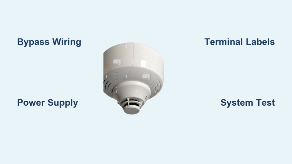
A single miswired terminal in a commercial smoke detection network can render an entire fire safety system useless. If one detector fails to send a signal, the whole chain breaks, and lives may be at stake. This makes correct wiring practices absolutely essential for anyone handling commercial smoke detector installation.
Below, you’ll find a complete walkthrough covering bypass wiring, power supply selection, terminal identification, and final safety verification. Whether you manage an office, warehouse, or retail facility, these steps ensure your system performs reliably when it matters most.
Bypass Wiring for Interconnected Detection
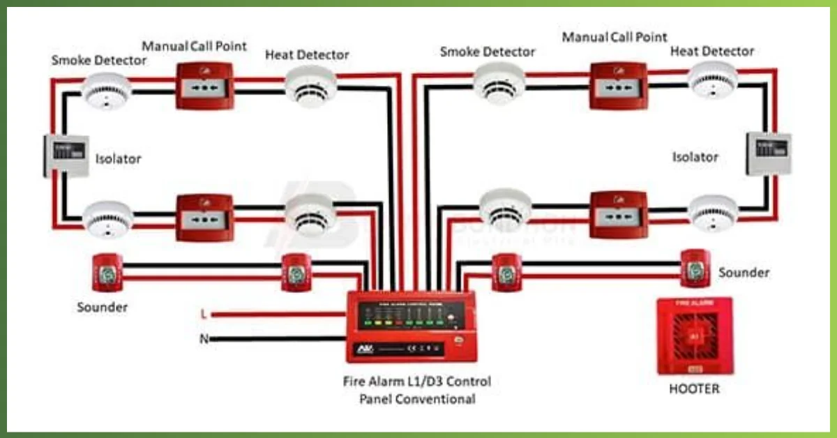
Interconnection lets one triggered unit activate every detector in the building. Without it, a fire in a remote hallway could go unnoticed until it spreads. Bypass wiring solves this by linking each detector in a signal-sharing circuit.
Connect the Bypass Wires Correctly
Every detector includes two terminals dedicated to interconnection. The white wire attaches to Terminal #1, while the red wire connects to Terminal #12. These wires carry the activation signal from one unit to the next.
Chain Detectors in Sequence
Detectors must be wired in a daisy-chain configuration. Begin by running red and white wires from Terminals #1 and #12 of the first detector to the same terminals on the second detector. Continue this pattern through the third and fourth units.
Pro Tip: Install detectors in logical order, such as following airflow paths or room sequence. This makes future troubleshooting far easier when technicians need to trace the signal path.
Verify Signal Continuity
After making each connection, trace both wires to confirm no breaks or misroutes exist. A multimeter can confirm continuity between corresponding terminals. Label each detector (Unit 1, Unit 2, etc.) right away to support long-term maintenance.
Power Supply Options for Reliable Operation
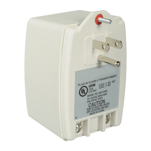
Smoke detectors support several voltage inputs, and choosing the right one ensures stable performance and code compliance. Your facility type will largely determine which option fits best.
120V AC for Standard Commercial Buildings
Most offices, retail stores, and mid-sized facilities rely on 120V AC power. Draw electricity from a dedicated circuit at the main electrical panel to prevent overloads. Feed the first detector directly, then branch power to each downstream unit.
240V AC for Industrial Environments
Warehouses, manufacturing plants, and large-scale HVAC systems often require 240V AC. Only use detectors rated for this higher voltage, and always hire a licensed electrician due to increased shock risk.
24V AC/DC for Low-Voltage Integration
When integrating with building automation systems or low-voltage HVAC controls, 24V AC/DC works best. A transformer typically connects this supply to the main electrical system, enabling seamless communication with thermostats and fan relays.
Battery Backup for Emergency Coverage
Even reliable power sources fail. Built-in lithium batteries last between 5 and 10 years and provide temporary operation during outages. Some jurisdictions require external backup systems to meet continuous-operation codes.
Best Practice: Combine line voltage with battery backup whenever possible to satisfy NFPA 72 requirements for uninterrupted protection.
Daisy-Chained Wiring Layout and Signal Flow
A clean wiring layout supports both power delivery and signal transmission across every detector. Planning this layout carefully prevents signal loss and simplifies future repairs.
Power Each Detector Along the Chain
The first detector receives direct power from the source. At each junction, the power line splits to feed the next unit. Maintain consistent polarity and label every wire to avoid confusion during service.
Maintain Bypass Signal Integrity
Bypass signals travel independently from power lines. Even if one detector loses power, upstream units can still trigger downstream alarms if the wiring is correct. Avoid splicing bypass wires inside junction boxes unless those junctions are enclosed and clearly labeled.
Identify the Final Unit
The last detector in the chain has no outgoing red or white wires. It only receives input, with no connections leaving Terminals #1 or #12. Test its response during system verification to confirm it activates properly when upstream units signal.
Warning: Never loop the bypass signal back to the first detector. This creates feedback loops and frequent false alarms.
Terminal Identification and System Labeling
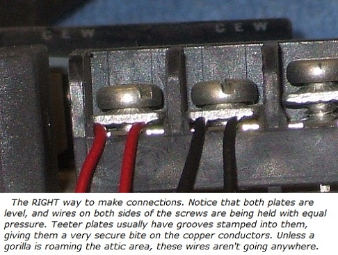
Correct terminal use prevents malfunctions and streamlines repairs. Each terminal on a commercial smoke detector serves a specific purpose, and mixing them up can disable critical functions.
Bypass Terminals
Terminal #1 (white wire) and Terminal #12 (red wire) handle interconnection. Use colored tape or printed labels to distinguish them from power and control terminals.
HVAC Control Terminals
Terminal #6 connects to the fan control relay, while Terminal #16 interfaces with the thermostat shutdown circuit. These terminals trigger automatic HVAC shutdown during fire events, a critical function for limiting smoke circulation.
Alarm Output Terminals
Some models include dedicated alarm relay terminals. These trigger external horns, strobes, or building management alerts. They are not required for basic operation but matter greatly for full fire panel integration.
Expert Note: Terminal configurations vary by manufacturer and model. Always consult the equipment manual before making any connections.
On-Site Detector Labels
Affix numbered tags during installation and record each location on a site diagram. Include voltage type and circuit number on the label itself. This saves significant time during inspections and emergency repairs.
Final Installation Safety Checks
Before energizing the system, a thorough inspection prevents hazards and confirms reliable operation. Skipping this step risks short circuits, false alarms, or total system failure.
Double-Check Every Connection
Confirm each wire is secured to the correct terminal. Look for stray strands that could bridge adjacent screws, and match every connection against the manufacturer’s schematic.
Common Mistake: Reversing the red and white wires disrupts signal flow and may prevent interconnection entirely.
Inspect for Exposed Conductors
No bare copper should remain visible outside terminal blocks. Use wire nuts or insulation sleeves where needed, and ensure covers fit flush without pinching any wires.
Confirm Power Is Off Before Testing
Lock out the circuit breaker throughout installation. Use a voltage tester to verify zero power at the first detector before touching any terminals. Restore power only after every connection is complete and verified.
Secure Detector Covers
Snap or screw each cover firmly into place. Confirm seals remain intact to keep out dust and moisture. Avoid overtightening screws, which can crack the housing.
Test System Response After Energizing
Once powered, press the test button on the first detector. All downstream units should sound alarms within 2 seconds. Repeat the test on the final detector in the chain. Confirm that indicator lights remain steady on every unit.
Compliance and Maintenance Best Practices
A successful installation does not end at power-up. Ongoing compliance and routine care keep the system functional for years.
Follow Local Fire Code Requirements
Some jurisdictions require annual certification of commercial fire systems. Permits may be necessary for new installations or major modifications. Always use UL-listed components and approved wiring methods.
Schedule Regular Inspections
Test detectors monthly using the built-in test function. Clean units quarterly to prevent dust buildup, a leading cause of false alarms. Replace detectors after 10 years or according to manufacturer lifespan guidelines.
Document the Installation
Keep a wiring diagram on-site along with circuit breaker numbers, voltage type, and total detector count. Update records after any modifications or repairs.
Plan for Future Upgrades
Consider smart detectors with remote monitoring for larger buildings. Reserve space in junction boxes for future expansion. Use conduit rather than NM cable where possible, since it allows easier upgrades later.
Frequently Asked Questions About Commercial Smoke Detector Installation
What wires connect smoke detectors together?
Commercial smoke detectors interconnect using a white wire on Terminal #1 and a red wire on Terminal #12. These wires carry the bypass signal from one detector to the next in the chain.
Can commercial smoke detectors run on 24V power?
Yes. Many commercial detectors support 24V AC/DC for integration with low-voltage control circuits. This option works well with building automation systems and HVAC controls.
How many smoke detectors can be daisy-chained?
The limit depends on the manufacturer’s specifications and local fire codes. Most systems support at least four detectors in a chain, though some allow more. Always consult the equipment manual before expanding the chain.
Why is my interconnected smoke detector not triggering others?
Common causes include reversed red and white wires, loose terminal connections, or breaks in the bypass circuit. Test continuity with a multimeter and verify each wire lands on the correct terminal.
Do commercial smoke detectors need battery backup?
Most codes require battery backup to ensure continuous operation during power outages. Built-in lithium batteries typically last 5 to 10 years, though some jurisdictions require external backup systems.
How often should commercial smoke detectors be replaced?
Replace detectors every 10 years or per the manufacturer’s recommended lifespan. Monthly testing and quarterly cleaning help extend reliability, but components degrade over time and must be renewed.
Key Takeaways for Commercial Smoke Detector Installation
Successful installation rests on three pillars: correct bypass wiring, proper power supply selection, and thorough final testing. Always verify continuity between terminals, use a dedicated circuit for power, and label every detector on-site. Compliance with local fire codes protects both lives and legal standing, so document everything and schedule routine inspections.
Your next step is simple: review the manufacturer’s terminal chart for your specific detector model, gather the necessary wiring tools, and walk the building to plan your detector placement before pulling any wire.